- Function:This Motorcycle Gauge also can increase reaction sensitivity for improved safety.
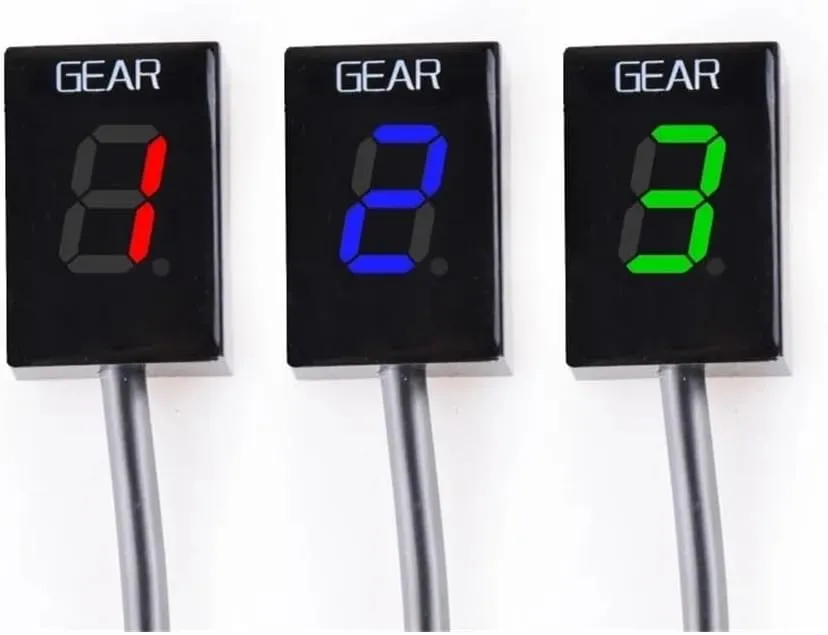
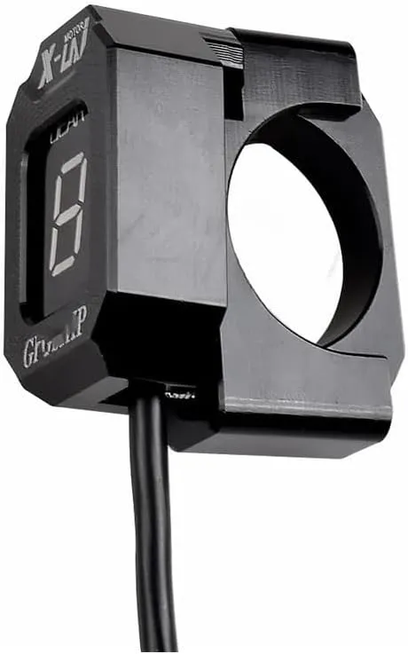
- Features:Motorcycle Speed Display Mater Gear indicator by better understanding the gear shifting situation, the rider can better adjust the speed of the car, thus greatly reducing fuel consumption.
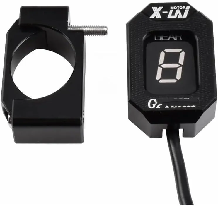
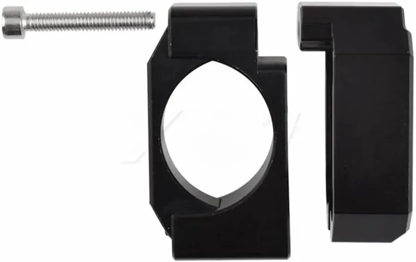
- Features:Motorcycle Display Speedometer Using materials and workmanship, the overall structure is strong and can withstand heavy use.
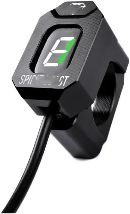
- The Motorcycle Gear Display can remind you of the current gear to make riding safer.
- The Motorcycle Gear Display perfectly into the look of your motorcycle.
For Daelim ALL With Digital Trip / ODO ALL YEARS Motorcycle 1-6 Level Gear Indicator Digital Gear Meter
For Daelim ALL With Digital Trip / ODO ALL YEARS
Installation:
Locate the Speed Sensor connector
Confirmation:
1. Separate the Speed Sensor connector (you might need to use a small flathead screwdriver to get the connector apart). Rotate the rear wheel while ignition is on. The speedometer should indicate 0. If so, turn the ignition off and proceed to the next step. Otherwise, if the speedometer registers a speed other than 0, you have not disconnected the correct coupler and need to look again.
2. After separating the Speed Sensor connector, in both the male and female 3-pole GFYSHIP harness connectors. Make sure the connectors are fully seated.
3. Find RPM/Timing Sensor (Pickup) connector. The sensor is mounted either on top, or the side of the crankcase. Trace the cable from the sensor until you find the 3-pole connector. Here is the connector location on some popular models: , Multistrada: At the left side, above horizontal cylinder, ziptied to frame. S4RS: Behind left side cover under seat. ST3: At the right side of engine, zip-tied to frame.
4. Disconnect the connector, and pull the LARGER rubber boot from the, to leave the three wires exposed.
5. Route the GFYSHIP Black/Green wire through the rubber boot from the. Make sure the wire will NOT touch the exhaust pipe or cylinder block.
6. Connect the GFYSHIP Black/Green wire to the wire in connector slot position 1, using the Red wire tap connector supplied. Usage: Place the unstripped run wire (slot position 1) inside the run channel. Close the side cover until latched. off the excess length, then insert the unstripped tap wire (Black/Green) completely and check its position. Insert the blade (u-contact) and press down by finger pressure. Then, fully depress the u-contact with pliers. Close the hinged top cover unt
Thank you for your attention.If you have


